In Project Two, I tried changing the facade color according to sunlight direction and semi-auto control color distribution.
The first thing I did was making a new mass model rather than using the old model. It is because the old model has too many separated curtain panels and they have weak relationship with each other. So I made this new conceptual mass model below. (Left is the new model)
On this mass model, I inserted a surface pattern called "panel 1", which is made in another family. The grid lines were distributed accordingly to having closer value of panel dimensions.
The first try I did was making the color of the facade changing with the sunlight direction. So I started with using Dynamo.
In the first step, I used these nodes to find the curtain panels in the project. In dynamo it is called the element. The central points were located by giving 0.5 value to the U,V value.
Next, I made these nodes to relate the sunlight with the midpoints of the panels. In the list of every value, it has negative and positive values, that is why the absolute node was put in this group.
The third step is to set the color for reflecting the sunlight. I chose blue and red and used a number slider to control the darkness of the color.
This is the last step to realize the color on the building facade.
Here is the result.
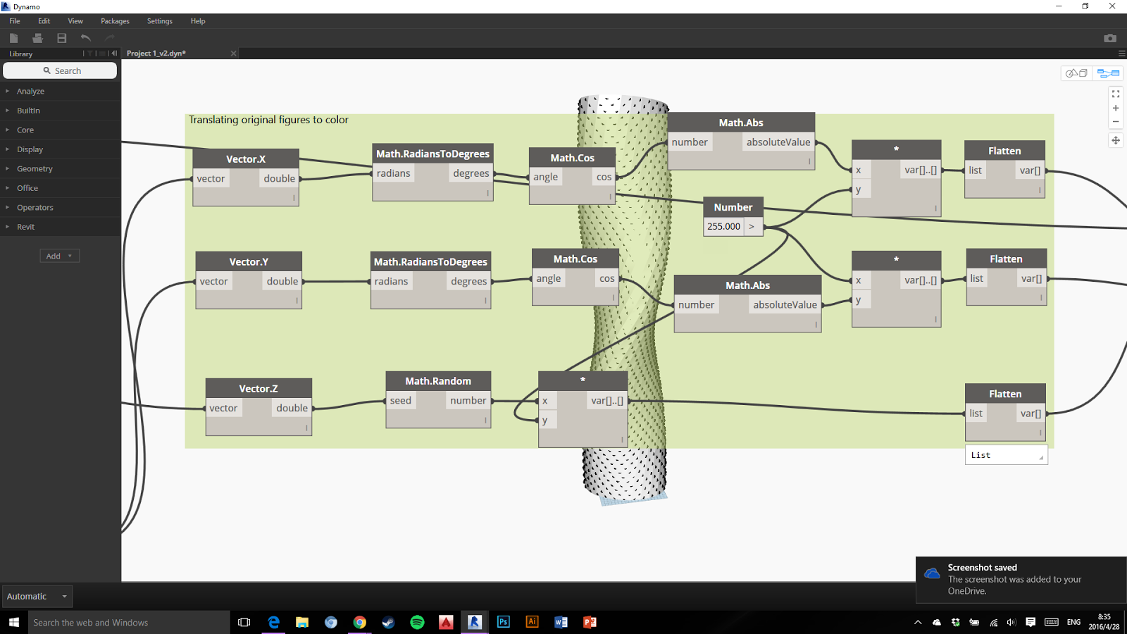
The second try was making the color of the curtain panels being able to change according to a semi-auto controlled factor. It's still in Dynamo.
In this group the vector was controlled by two points. These two points are on the diagnal of the panel and the U,V values adding together as 1. The two point have the opposite value of U and V.
The X and Y values of the vector were translated into a wave defined by a cos formula. Which makes the value varied from 0-1 as they have been changed to absolute value. The Z value was associated with the height of the points because the difference between two points were too small in one panel.
The X, Y values turned into red and blue and the Z value connected to the alpha value.
Shen Jun,
Robert Groessinger, Florian Pucher, Yi Wenzhen, Hao Yi, Yao Mengyao, Zhao Fan,
Liu Yuan, Zhao Wei, Li Kunjuan, Yu Kui, Max Lonnqvist, Eric Spencer
Associate Architects
BURKA
Architects INC.
Structural Engineer
SIGMUND,
SOUDACK & ASSOCIATES INC.
Mechanical Engineer
ECE Group
Electrical Engineer
ECE Group
Landscape Architect
NAK Design
Interior Designer
ESQAPE Design
Client
Fernbrook /
Cityzen
Project Year
2012
Modernism has a famous
motto: A house is a machine for living in. However, as we progress further away
from the machine age, we are left with a question: what message should
architecture convey? What is the house of today?
Like other fast developing
suburbs in North America, Mississauga is seeking a new identity. This is an
opportunity to respond to the needs of an expanding city, to create a
residential landmark that strives for more than simple efficiency and that
provides residents an emotional connection to their hometown.
In place of the simple,
functional logic of modernism, our design expresses the complex and multiple
needs of contemporary society. This building is more than just a functional
machine: it responds to the significance of being located at the junction of
two main streets, elegantly bearing its landmark status and acting as a gateway
to the city beyond. It is something beautiful, sculptural and human.
Despite its landmark status,
the emphasis is not solely on height. Our design features a continuous balcony
that surrounds the whole building, eliminating the vertical barriers traditionally
used in high rise architecture. The entire building rotates by different
degrees at different levels, corresponding with the surrounding scenery. Our
aim is to provide 360 degree views for each residential unit, and to get city
dwellers in touch with the natural elements and reawaken their appreciation of
nature.
The Absolute Towers are
nicknamed as “Marilyn Monroe Towers” by the locals for the sinuous shape.
Tower A: 45,000sqm,
56stories/ height 170m
Tower B: 40,000sqm,
50stories/ height 150m
The larger of the two towers twists 209
degrees from the base to the top, making it very similar to Turning
Torso in Malmö, Sweden. The structural design was done by Sigmund Soudack & Associates Inc, a
Toronto-based structural engineering firm. The tower has six levels of
underground parking.
The following table lists the amount of rotation
for each floor of Tower 1.
Floor
Rotation
Floor
Rotation
Floor
Rotation
Floor
Rotation
Ground
-10°
15
15°
29
74°
43
168°
2
-9°
16
18°
30
82°
44
171°
3
-8°
17
21°
31
90°
45
174°
4
-7°
18
24°
32
98°
46
177°
5
-6°
19
27°
33
106°
47
180°
6
-5°
20
30°
34
114°
48
183°
7
-4°
21
33°
35
122°
49
186°
8
-3°
22
36°
36
130°
50
189°
9
-2°
23
39°
37
138°
51
192°
10
0°
24
42°
38
146°
52
194°
11
3°
25
45°
39
154°
53
195°
12
6°
26
50°
40
159°
54
196°
13
9°
27
58°
41
162°
55
197°
14
12°
28
66°
42
165°
56
198°
First I started building a line in the conceptual mass model. This is the reference line for each floor where the central point of the ellipse shape. Because there are 56 levels of the building, I separated the line into 55 parts, which have 56 points indicated where the floor slab will be at.
The next step is to create the basic adaptive ellipse shape for the floor slabs. In this case, I started building the model in the adaptive conceptual mass model. On this stage, the turning angle of the basic ellipse shape should be relevant to the height of the level. Thus, I created a parametric instance value for this model, which was named "H".
In the picture above you can see that there are three more relevant values. "a" and "b" stand for the shorter axial length and the longer axial length of the ellipse. And these two values were constrained. The third value of the model is the rotation angle. This is the key of the formation of the building shape. In order to make the shape being able to turn "automatically", a formula was put in the parameter value blank. After studying the regularity of the rotation, (2 * atan((H - 285') / 200') + 180°) * t was filled in the spot. This formula looks like the picture showed below.
As you noticed, there is a "t" being multiplied at the end of the formula. The "t" is actually a type parameter in order to allow the user to change the shape of the building more easily.
Another vital hint here is the angle annotation and the length annotation should all be constrained to the central point. Also, these reference annotations and reference lines should be created before the shape being created.
After finishing the adaptive model, it comes to the third step. I duplicated the ellipse 55 times to put them on each reference points on the line after loading the adaptive model into the general conceptual model. Then I change the value "H" of each level. While this was happening, the ellipse would turn to a certain angle according to the value of "H".
The last step is creating the building facade. I loaded this conceptual mass model into a project and set different level of elevations referring to the level of the ellipse shapes.
Then on each level, I created a place-in-model blending component. This component is the curtain wall of each level. Finally, I set the materials for the floor slabs and the curtain walls.
Here are some renderings.


